In practice
- Select a coordinate system with the least distortion for your project area
- When working across states or continents, the distortion (aka error) could be very large
- If you are unsure what CS to use, look to see what coordinate system the ‘experts’ use when working in the same area
- For most small area projects, the State Plane or UTM coordinate systems are equally good
- If project overlaps state boundaries, UTM is often a better choice
- It is important to make sure all data and all people (on a given project) are using the same coordinate system
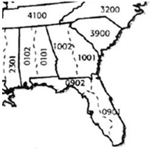
The state plane coordinate system
- Each US state has at least one state plane zone
- Some states have multiple zones (Georgia has ‘east’ and ‘west’ State Plane zones)
- Uses either the Transverse Mercator (north-south oriented states) or Lambert Conformal Conic (east-west oriented states)
- Georgia State Plane uses the Transverse Mercator map projection
- Tennessee State Plane uses the Lambert Conformal Conic map projection
- Uses feet as its native unit of measurement
- Traditionally used the North American Datum of 1927 (NAD27)
- Not sure which SP zone you are in?
https://hub.arcgis.com/datasets/esri::usa-state-plane-zones-nad83/
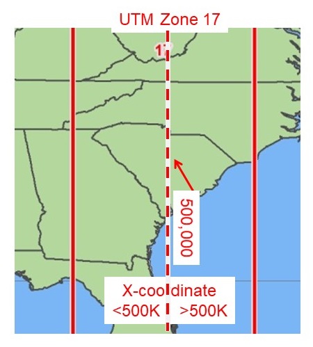
The Universal Transverse Mercator (UTM) coordinate system
- Earth split into 60, 6-degree zones
- eastern Georgia is in UTM zone 17
- western Georgia is in UTM zone 16
- Measurements are made in meters
- The X coordinate of the center of every UTM zone, the central meridian, is arbitrarily set to 500,000m
- as you move eastward, the X-value increases
- as you move westward, the X-value decreases
- The Y coordinate is the distance from the equator, measured in meters

- Utilizes the NAD 1983 datum
- Not sure what UTM zone you are in?
Five opportunities to interact with coordinate systems in ArcMap…
- Your layer’s defined coordinate system
- Your data frame coordinate system
- The DEFINE PROJECTION command
- The PROJECT command
- The PROJECT RASTER command
Your layer’s defined coordinate system
This is the coordinate system that was used when creating the data.
Imagine a point layer you create using GPS. Before you begin your data collection, you intentionally change the settings on your GPS to store XY locations using the State Plane Georgia East coordinate system. The defined coordinate system of this GIS layer is, State Plane Georgia East.
If, for example, you digitize a property based on what you see on the NAIP aerial photographs, then those resulting layers will inherit the aerial photograph’s coordinate system.
Two easy ways to figure what coordinate system your layer is using is to 1) read the associated metadata or to 2) ask the creator of the data “what coordinate system is this layer using?”
The data frame coordinate system
ArcMap will automatically ‘project-on-the-fly’ your GIS layers to match the assigned data frame coordinate system. You access the data frame coordinate system by View > Data Frame Properties > Coordinate System tab. This is why our Lat/Long layer overlaid our land cover layer last week.
The DEFINE PROJECTION command
If you have a layer with an ‘Unknown Spatial Reference’ (an ArcMap pop-up will let you know if this is the case), you should use the DEFINE PROJECTION tool. This tool does NOT change a layer’s coordinate system and it does not create a new layer; this tool only changes the associated metadata so ArcMap can correctly display the data.
The PROJECT command
When performing an analysis, you need to ensure all of the inputs are cast in the same coordinate system. The PROJECT command to ‘mathematically transform data from one coordinate space to another’. This command does create a new layer so you should use a smart naming convention.
The PROJECT RASTER command
The above rule of thumb also applies to raster data. If you are performing a raster analysis, you need to ensure all layers are cast using the same coordinate system. Use the PROJECT RASTER command to mathematically transform your rasters from one CS to another.