Vector Data Creation – Digitizing I
Digitizing: “the art and science of connect-the-dots” (Lowe 2016)
Digitizing in ArcMap is fairly simple. You:
- create a point, line, or polygon feature class (inside your file geodatabase)
* this includes adding the appropriate fields in the attribute table - load a georeferenced data source (NAIP aerial, GPS data, …)
- verify your VIEW DATAFRAME COORDINATE SYSTEM IS SET TO MATCH YOUR GEOREFERENCED DATA
- start an editing session, load the editing tools
- select your edit feature in the ‘Create Features’ window
- trace your feature(s) of interest – digitize
- attribute each feature
- end your editing session
I created a digitizing YouTube channel a while back that you might find useful (Digitizing into a file geodatabase).
Step-By-Step:
Create your feature class
Before you begin, you need to decide what type of vector features you will be creating (points, lines, polygons) and what attributes you will store for each. If you are digitizing points, you might store an attribute called ‘thetype’ which is a description of the object at that location and one called ‘thecondition’ which is a ranking of how well the object has been maintained. If you are digitizing polygons, you might want to store ‘covertype’, ‘age’, and ‘conditionclass’.
The fields you add later on MUST contain no spaces, no strange characters (only a-z, 0-9, and underscore)
- create your file geodatabase
- create your feature class(es)
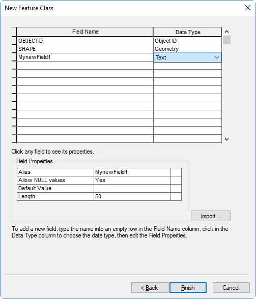
- right-click on your file geodatabase >> New >> Feature Class
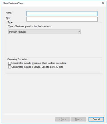
- Ensure you select the correct type (polygon/line/point)
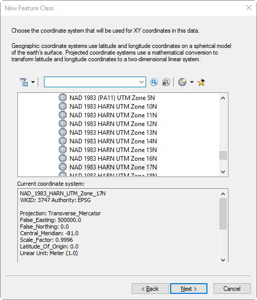
- Specify your coordinate system – this needs to match the CS of the georeferenced data source you load next (UTM or State Plane, and sometimes Lat/Long)
- For the most part, we will use the UTM/NAD1983/Zone 17N or Zone 16N coordinate system in this class. UTM/NAD1983/Zone 17N is suitable for areas in Georgia and along the east coast that are east of Atlanta. UTM/NAD1983/Zone 16N is suitable for areas in Georgia west of Atlanta and parts of Alabama, west/central TN, panhandle of FL, …
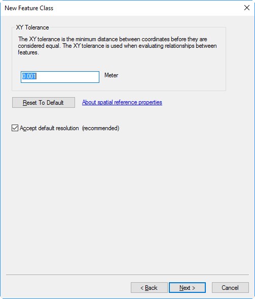
- Leave the XY tolerance as default
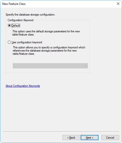
- Leave the ‘…database storage configuration’ as default
- Add your new fields
- right-click on your file geodatabase >> New >> Feature Class
Load georeferenced data source
- Suitable georeferenced data layers are NAIP aerials or many other data sets you download from the NRCS, GPS data you collect, a georeferenced raster or vector layer another sends you, …
Set the data frame coordinate system to match your georeferenced data from above
There are several ways to determine the coordinate of your georeferenced data. You can look at the layer’s Source tab (right-click on the layer >> Properties), you can view the georeferenced data’s metadata, you can ask the creator of the data.
- View >> Data Frame Properties >> Coordinate System tab: set the projected CS to match
Start editing and load the editing tools
At this point, you should have your georeferenced layer and the new feature class(es) loaded. To “start editing”
- right-click on your feature class >> Edit Features >> Start Editing
- if the Edit Toolbar does not automatically open (right-click in the grey area along the top of the screen >> select Editor)
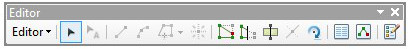
- From left-to-right
- Editor drop-down
- edit tool
- (5 greyed-out buttons)
- vertex editor
- reshape tool
- cut tool
- (greyed-out button)
- rotate tool
- (skip next two)
- create feature button
Select your edit feature in the ‘Create Features’ window
Open the Create Features window by clicking on the create feature button noted above or (Editor drop-down >> Editing Windows >> Create Features)
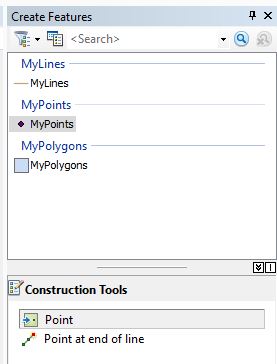
If you need to add a point, click on the point layer in the top section of the Create Features window and select ‘Point’ in the bottom section:
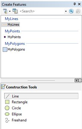
If you need to add a line, click on the line layer in the top section of the Create Features window and select ‘Line’ in the bottom section
If you need to add a polygon, click on the polygon layer in the top section of the Create Features window and select ‘Polygon’ in the bottom
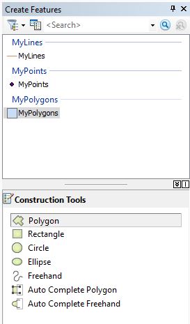
The ‘Auto Complete Polygon’ tool lets the user append a new polygon to an existing polygon
Trace your property boundary- digitize
You want to start by digitizing the exterior boundary
- zoom into your starting point (~1:3000 or larger)
- click once to start a feature >> slowly click around the boundary >> double-click to close your feature
Cut your boundary into pieces
- Load the EDIT toolbar: right-click in the grey area at the top of ArcMap > check next to Edit
- Use the ‘cut’ tool to cut your selected polygon into two parts
- Select the next part and cut it into pieces
- Digitize an island polygon by looping over the line you’ve digitized
Use the ‘reshape’ tool and the ‘vertex’ tool for fine tuning
Attribute each feature
(demo)
End your editing session and SAVE your edits
Editor pull-down-menu >> Stop Editing
a